Photo credit to Ivan Remonte
My aspirational arms, pictured above.
In November of 2022, I started taking a medication that elevates the risk of tendonitis and myopathy (pain in the muscle bellies and tendons respectively). Over the next 6 months I made friend's with my physical therapist, I saw him so much. In June 2023, I discontinued the medication and the tendonitis remained a problem in the left knee, specifically on the quadriceps tendon below the patella (kneecap bone). By Sept 2023, the knee was not improving much but also not debilitating. At the advice of my PT, I decided to add a leg extension machine to my home gym. I designed and built the first version with 2D CAD drawings that I assembled in my head. I quickly reached the limits of my brain power using that strategy and so I designed version 2 in 3D CAD software. It was my first time successfully using 3D CAD of any kind so it was slow and painful. The drawings here are drawings by me of the very first thing I drew in 3D CAD. Therefore, they should never be referenced as an example of best practices. I fully expect to be embarassed by these in a few years as I learn more.
During any multi-joint movement pattern, it is possible to accomplish the same motion with a variety of different muscles. Your body has redundant muscles. This is why some people can bench press super human weights with a fully detached pec major tendon even though the bench press is often thought of as a chest exercise. The triceps, pec minor, and front deltoids can do most of the work without the involvement of pec major. For the same reason, it is difficult to rehab tendons in the knee because your body can decide to use less quadricep and more of the surrounding muscles, thereby removing load from the quad tendon that is necessary to encourage healing. This is a reason why isolation movements (single joint exercises) are sometimes used in physical therapy. A leg extension cannot be done without putting load through the quad tendon.

[Caption] A commercial gym leg extension machine. Photo credit to bultovic.
The PT recommends multiple workouts of leg extensions every day. It is unlikely I will go to a commercial gym every day for months multiple times a day so I need one in the house. There are two varieties: cable pulley or swinging weight on a stick. The cable pulley machines apply a constant torque to the knee joint (or in some fancier models, a slightly variable torque to match the relative strength of the athlete). The swinging weight on a stick style applies zero torque at the bottom and 100% torque at 90 deg. Swinging weight on a stick is cheaper but less effective so I want a cable pulley machine. They cost $1,000 to $10,000 dollars and even if I had a spare $5k lying around, I do not have a place to put it.
The next best option is to attach it to my squat rack. There are lots of attachments available for a 3x3" post squat rack with 1" holes. Unfortunately, they are all swinging weight on a stick options. If I want a pulley-based leg extension as a squat rack attachment, I am building it myself.
My squat rack is already a frankenstein contraption. I own a power rack from EliteFTS and a selectorized cable weight stack from Rogue Fitness that I built a structure for and then bolted to my EliteFTS rack. I cut the brackets from Rogue apart with an acytelene torch and welded them into a configuration compatible with my rack. It is a bit unnerving to unbox a $1,300 kit of gym equipment and immediately start cutting it apart. However, like all things in life you can become habituated to taking perfectly nice, brand new, expensive things and breaking them on the way to making them better. (I once took a framing hammer to a $150,000 microscope so this was comparatively low stress. That worked too, though I did not personally own that microscope). My plan is to weld up something that I can attach to the rack with a hitch pin, like this lat pull down seat.
[Caption] My full squat rack is a combination of parts from EliteFTS and Rogue Fitness as well as my own welding/fabrication.
My idea was to have a steel supply company cut out the pieces on a plasma table and then I could weld them together. It's like designing your own lego set. Unfortunately, having no idea how to use 3D CAD, I took my little 2D CAD program and drew out some shapes that I could weld into a squat rack attachment. I also bought some 1.5" cold roll solid round bar (which only comes in 10' sections so I have 7' left over in the garage). This was all intended to work with these pillow bearings. They are cheap but the loads here do not require anything fancier so cheap is good enough in this case.
I have heard that a person's ability to rotate and visualize three dimensional objects is highly variable. For me, this is near the limit of the complexity I can handle assemblying my 2D drawings in my brain to make sure everything fits. Whether this is way too complicated or trivial for your brain to assemble is beside the point. The point is that this strategy puts an upper limit on the complexity you can handle. When I physically assembled it, I put the center plate in upside down. That may have been avoidable with a 3D sketch. This was definitely my limit.
This is the dxf file I sent to the steel company to cut from 1/4" plate. I also sent them a photo to indicate which pieces were keepers and what was waste.

This is the dxf file I send to the steel company to cut from 3/16" plate. It is just the outer wheel. I was trying to save money and weight so I had this one cut from thinner stock than the rest of the parts.
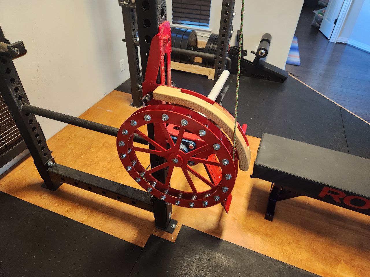
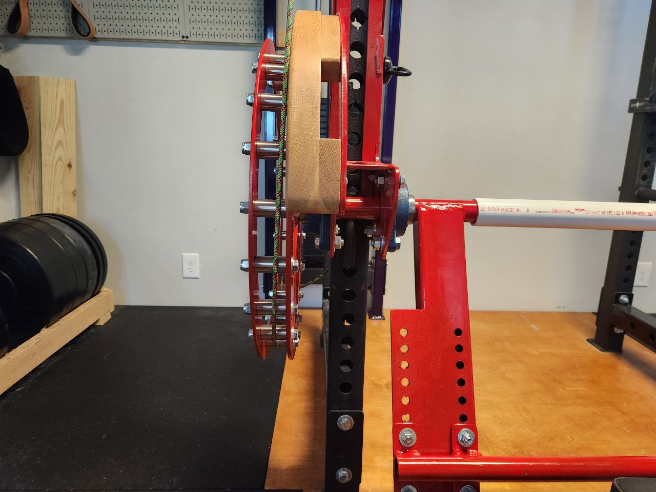
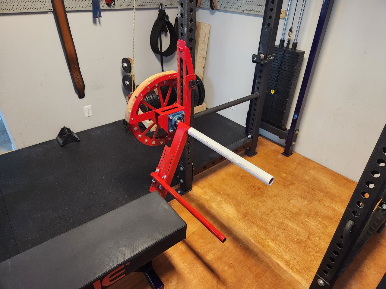
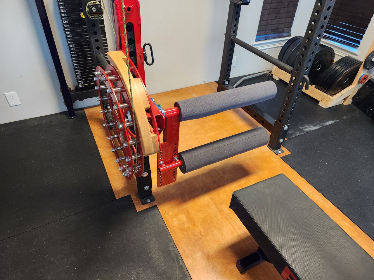
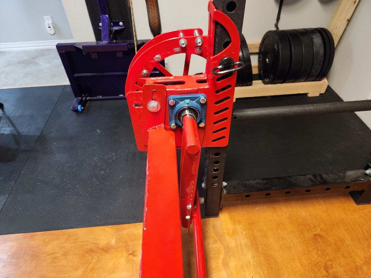
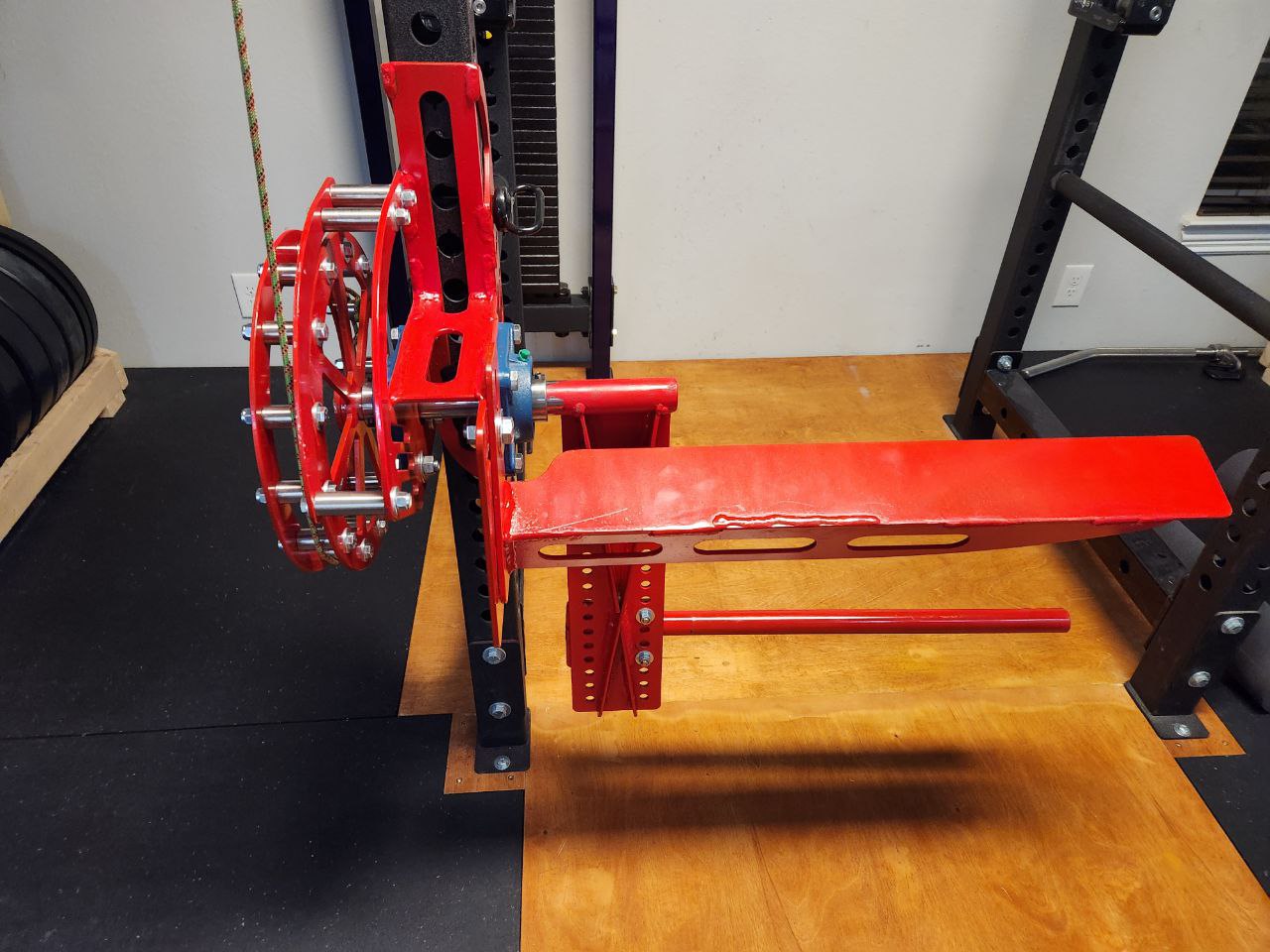
It worked pretty well. I added a piece of white oak to ensure the cable does not jump off the wheel. Given the shallow angle, I do not know if this is necessary because I never tried it without the oak but I could see it going either way. I also had some foam cut to fit over the bars; 4" OD on the ankle bar and 3" OD on the knee bar. The foam is a bit too squishy but it is far better than nothing.
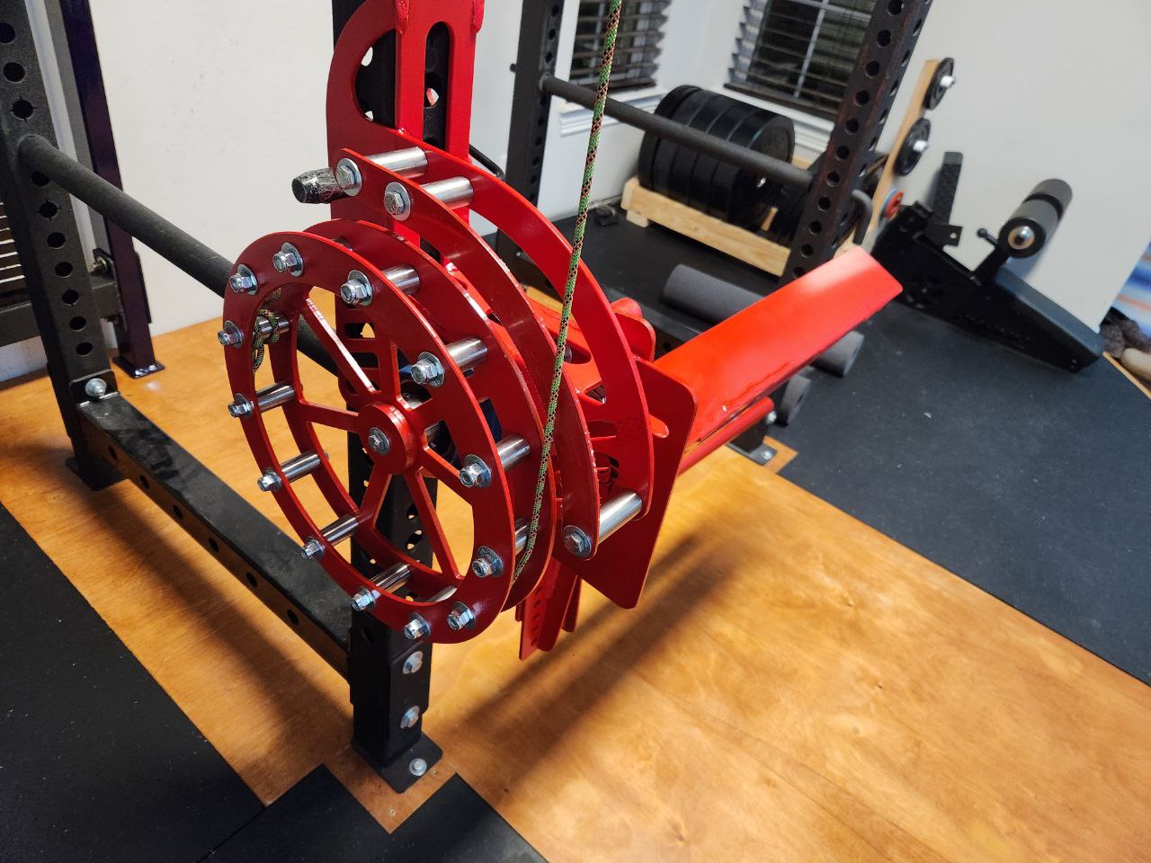
Normally we think of gym workouts in terms of a force through a lift. Sometimes, this force changes during the lift (ie bands and chains popularized by Louie Simmons and Westside Barbell) but we are still talking about force. Leg extensions and other isolation movements on machines where the machine applies a rotational force need to be conceptuallized in torque, not in force. If we double the size of the cam pulley, we would need half as much weight to apply the same torque. The force on the cable would be cut in half but the force in the quad tendon would be unchanged. My wheel is slightly larger than 9" radius where the cord lays over the pins. The weight stack is 20-300 lbs in 10 lb increments so this leg extension applies 15-225 ft-lbs of torque in 7.5 ft-lb increments. Looking back this is too large a wheel. Isolation movements are normally done for higher reps (10 to 50) and for me 50 to 100 ft-lbs of torque is enough. It would be much nicer if the increments were finer as well. If the wheel were 5 to 6 inches in radius, I would have 4 or 5 ft-lb increments and a max torque of 125 to 150 ft-lbs. My next version will have a smaller wheel.
This is when I downloaded FreeCAD. I had some previous bad experiences with CAD that gave me a bit of a block. Mechanical engineer friends had tried to show it to me only to immediately lose me with complexity I did not have any frame of reference for. I tried learning SolidWorks and AutoCAD when I had a student license only to give up after a week having drawn absolutely nothing. That happened at least four or five times. Then I tried FreeCAD a few times but early versions were so bug ridden or required complex dependencies that I never made the transition from 0 to 1. That transition is often the hardest part and in this case, I am both proud and ashamed to say that after a decade of knowing I should learn this, I have finally made the transition from 0 to 1. To be clear, I am not any good at CAD, but it is undeniable that I sketched my squat rack and the leg extension as I built it in version 1. Darren at the MangoJelly Solutions youtube channel was incredibly helpful in this adventure so I subscribed to his Patreon. Not sure if I could have done this without him.
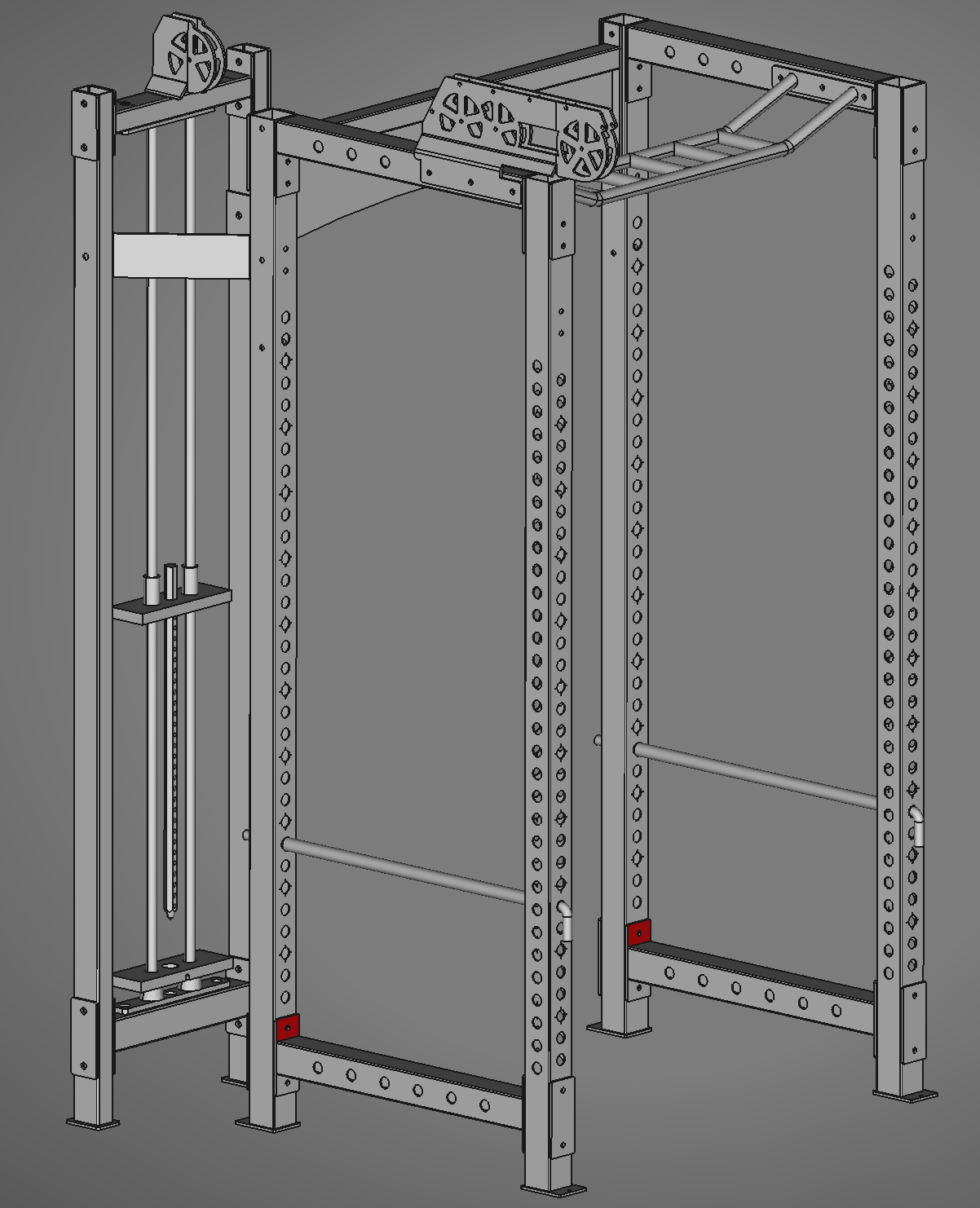
Here is the FreeCAD file of my leg extension attachment. It is compatible with any 3x3 squat rack with 1" holes (but could easily be modified to 5/8" holes). EliteFTS owns the intellectual property of the exact specifications of my squat rack so I deliberately did not make my drawing of it public.
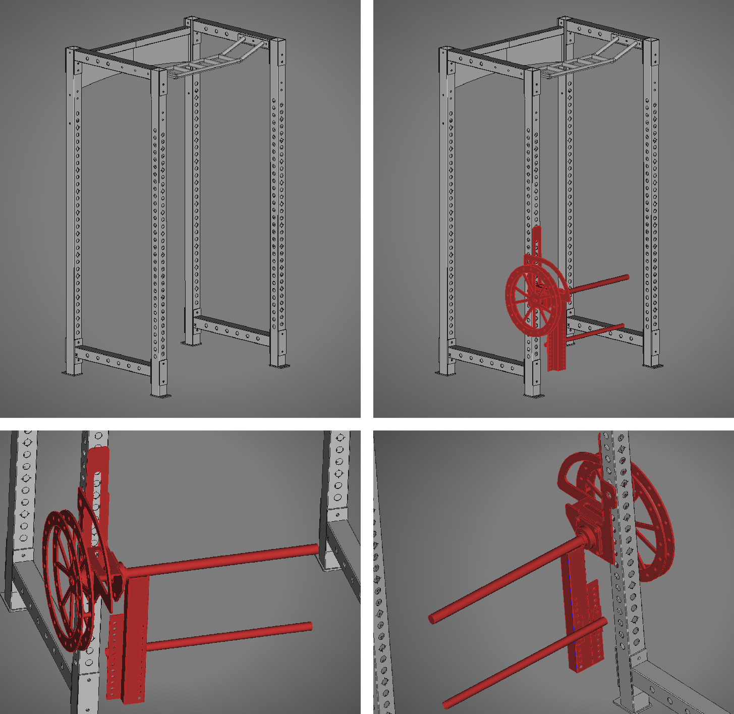
[Caption] [Upper left] Drawing of my EliteFTS squat rack. There are five small holes in a cluster at the back of the lower stretcher. These holes are not on the physical squat rack, they are just labels. The holes on the lower stretcher are 4.5" from the edge on one side and 5" from the edge on the other. I put the five holes in there to label the 5" side and make sure it was on the back of the rack. [Upper right] Squat rack with leg extension. The center plate is upside down because that is how I welded it together. It is upside down relative to what I intended when I made the 2D drawings. It is possible, I could have avoided this if I had seen this if I had a 3D drawing to work from originally. [Lower left] Zoomed in view of leg extension attachment. [Lower right] Zoomed in view of leg extension machine from the back.
After I built this, I found the top piece flexed a little so I welded on a couple side pieces to brace the top together a little better. Again, this probably would have gone better if I had designed the thing in 3D CAD from the beginning.
In version 2.0 I want the following things: (1) The cam wheel should be smaller so each pound of force on the pulley rope creates less torque on the knee. This will make the unit smaller/easier to move, and lower the max torque. (2) Drive wheel with more sensible hole pattern. Version 1 looks ugly to me. (3) The support under the knee should be provided by something other than the drive shaft. The knee should be supported such that the center of rotation of the knee joint aligns with the center of the drive shaft. (4) The connection between the drive shaft and the ankle bar should be cut from plate steel, not scraps I scavenged in the workshop. Drilling 28 holes is annoying. (5) The side plates should extend to the back of the posts for extra stability.
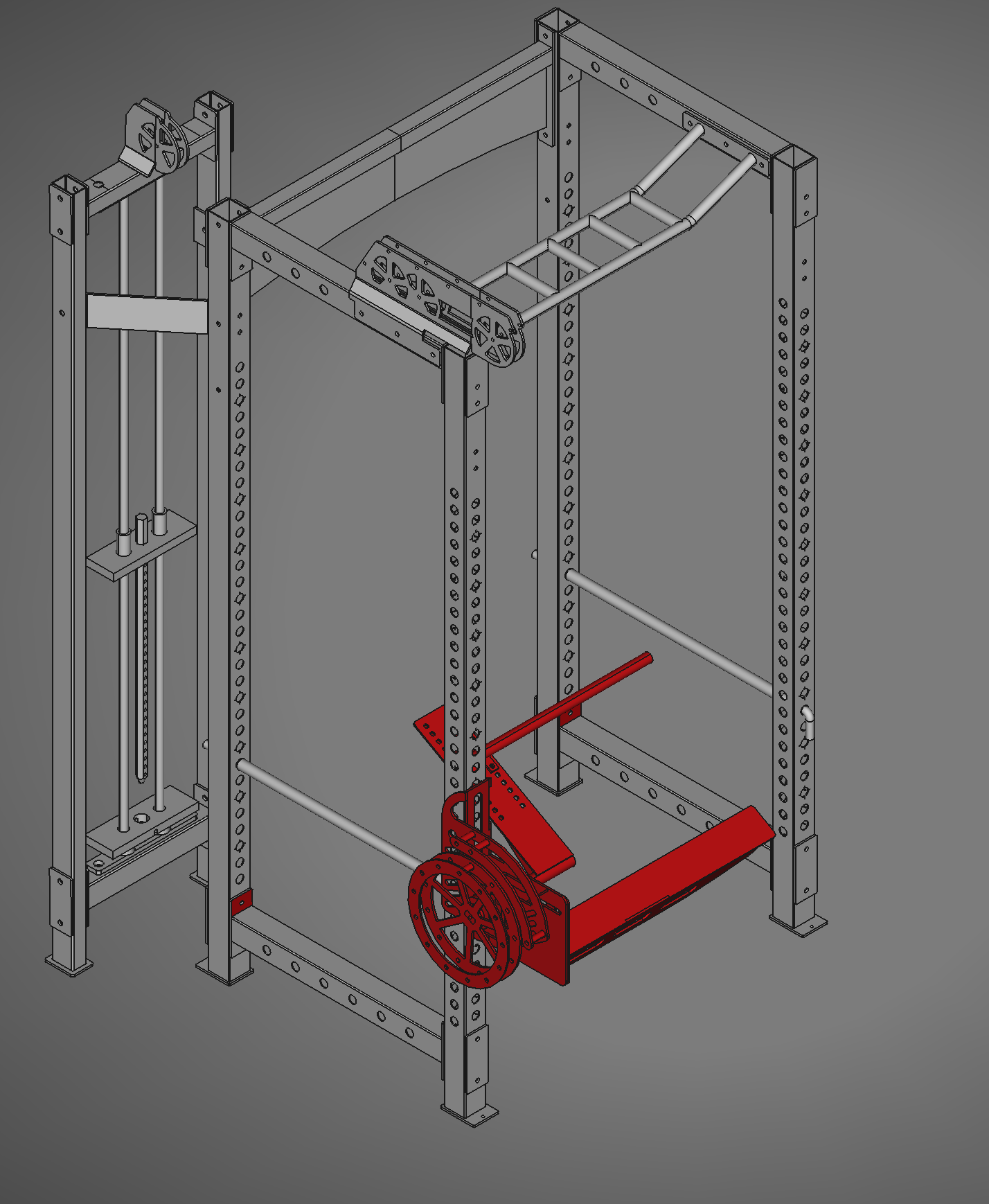
[Caption] Version 2 of the squat rack fixes some of the problems with version 1. This is a noteworthy project in my life because it is the first time I designed a project in 3D CAD before I built it.
The methods of construction were the same in version 1 and 2. I drew the shapes in CAD and sent them to a steel supplier to be cut on a plasma table. I welded them with 7018 rods in my garage and spray painted the final product red. The silver bits are stainless steel pipe, 1/2 dia, polished with a 2x72 grinder.
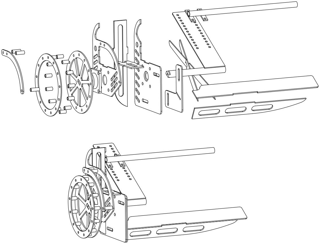
[Caption] An exploded view helps keep things straight during the assembly process. When assembling with a welder, things are little hard to undo after a mistake.